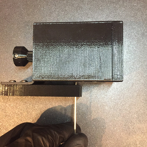
Step 3
Parts required:
- 1x 3D printed mounting plate with L bracket
- 1x AF3s with pulley
- 4x 6mm M3 bolts
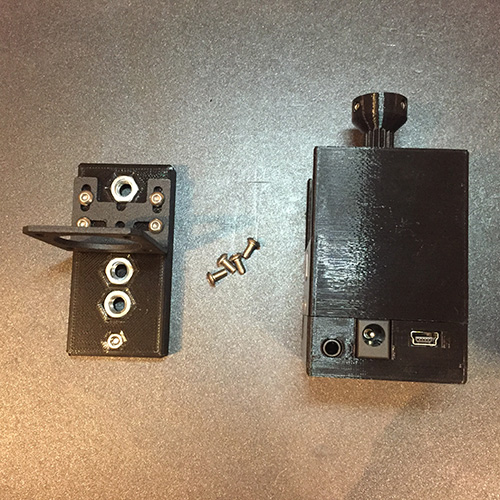
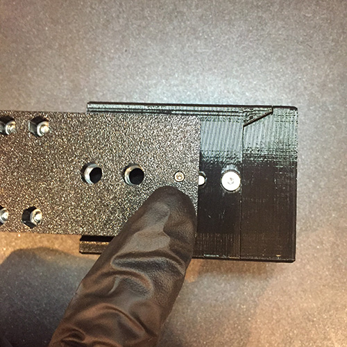
Put the motor on the straight surface so the shaft is facing upwards. Slide the L bracket
over the pulley so it rests on the motor enclosure like show on the photo.
Secure the L bracket with 4x M3 bolts. Before tightening the bolts, make sure the motor is
in the middle position inside L bracket M3 slots.
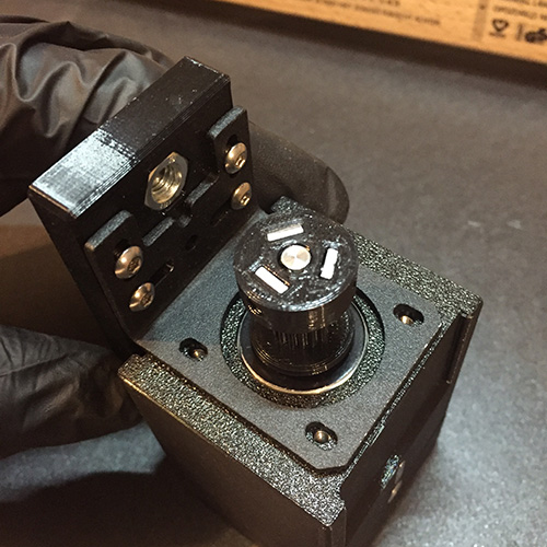
Flip the motor over and locate the M3 tensioning set bolt.
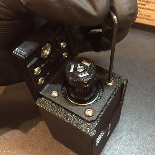
Now flip the motor on the side and bolt it until it barely touches the motor enclosure.